BLF 348 Teardown
I have carried a BLF 348 for a few months now, and while I really like the form factor (it very easily slips into my pocket/waistband), the mode selection leaves something to be desired. Which is to say, it has no modes; the 348 is either off or on and it is bright when it is on. On a whim, I decided to teardown my 348 and see how feasible a more flexible driver might be.
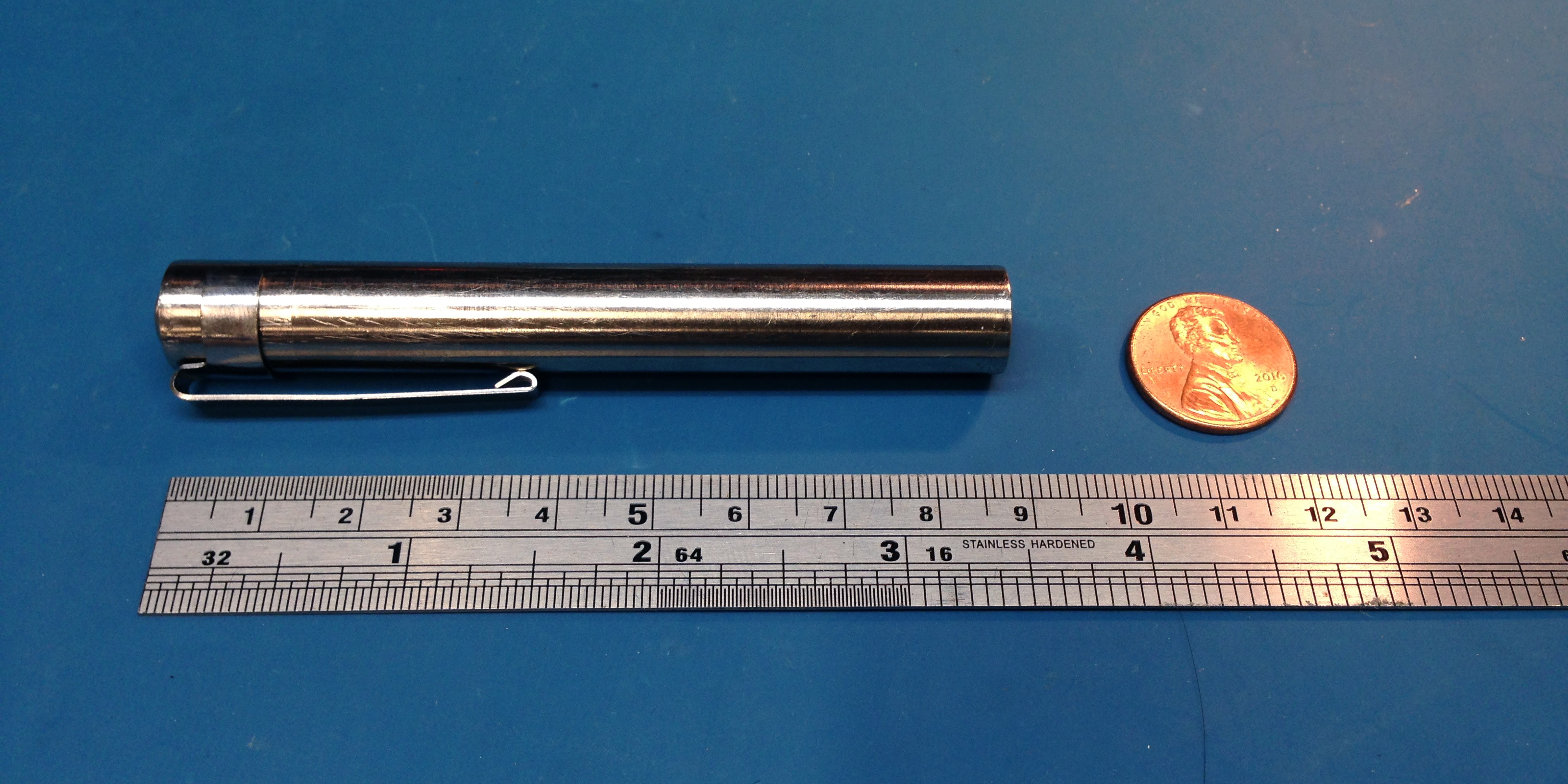
If you’re not familiar with the BLF 348, it’s a 1x AAA light that is sold in several emitter options (but the Nichia 219 is the nicest), several finishes, from multiple vendors. It originated from a BudgetLightForum group buy, but is generally available from GearBest for ~8USD or on Amazon for ~15USD. It has a rear reverse clicky switch, a single-mode buck driver, and a orange-peel reflector with a relatively deep bezel for a nice beam shape.
Teardown
|
|
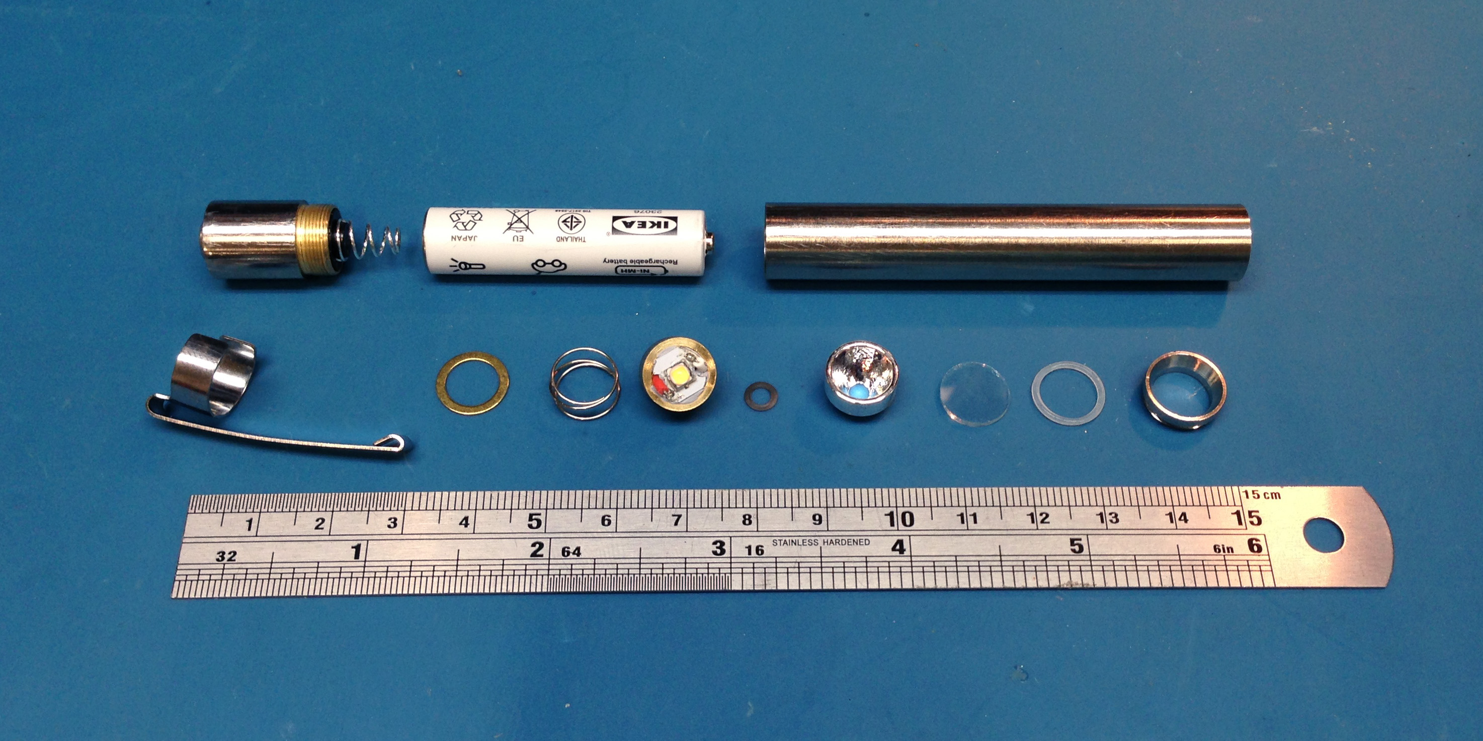
The 348 unscrews at both ends. The tailcap/switch assembly/spring is a single unit and is straightforward, nothing to lose. Unscrewing the front bezel requires some care. In order: front bezel, clear o-ring, glass lens, orange-peel reflector, black centering ring (of sorts) which may cling to the emitter, pill with driver and emitter PCBs, small spring, and brass washer (which sits on a very small ledge down in the 348 tube).
Various measurements:
- Reflector: 10.84mm dia, 6.63mm tall
- Pill: 10.78mm dia, 5.74mm tall
- Emitter PCB: 7.91mm dia, 7.33mm flat-to-flat, 0.92mm thick
- Driver PCB: 10.13mm dia, 1.02mm thick
|
|
|
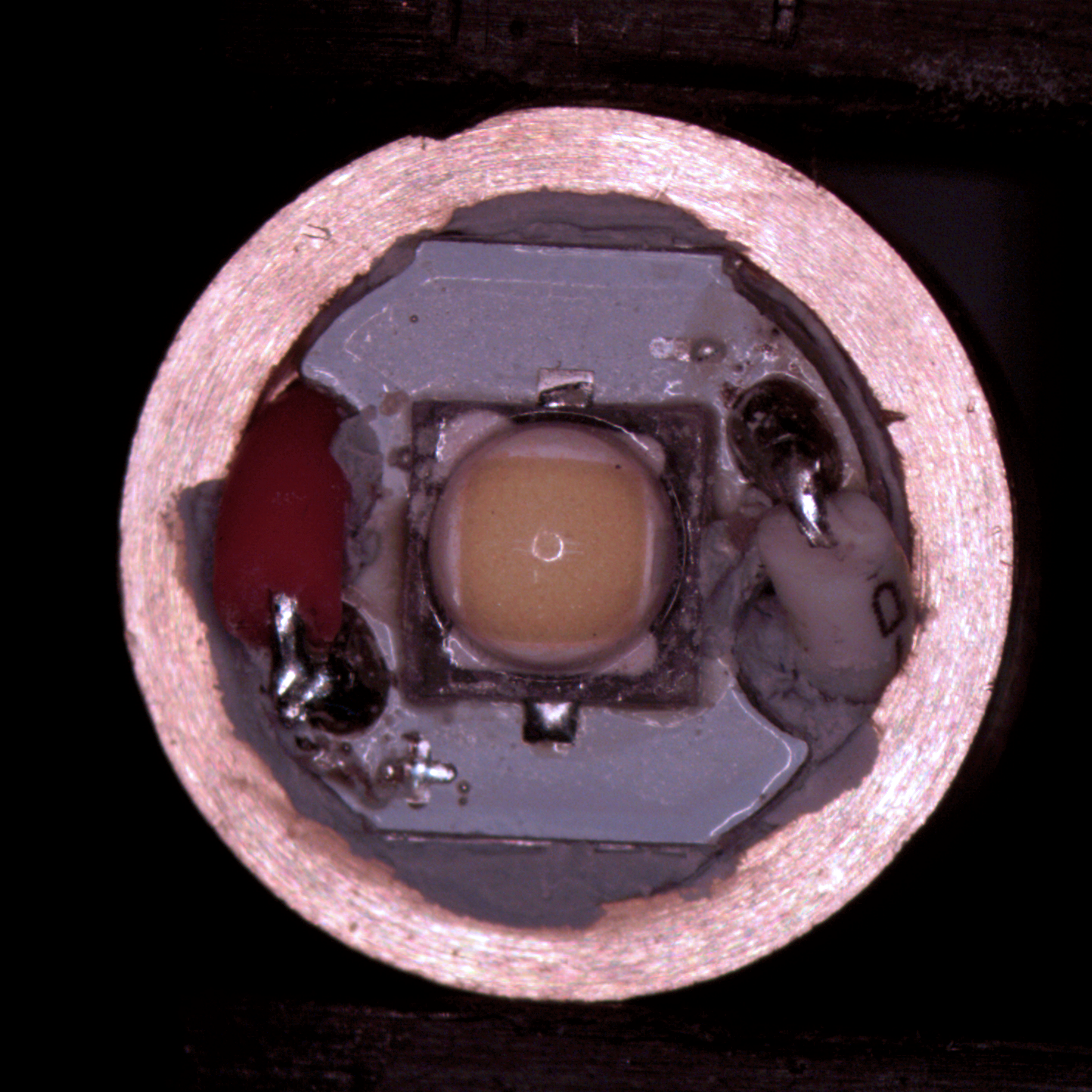
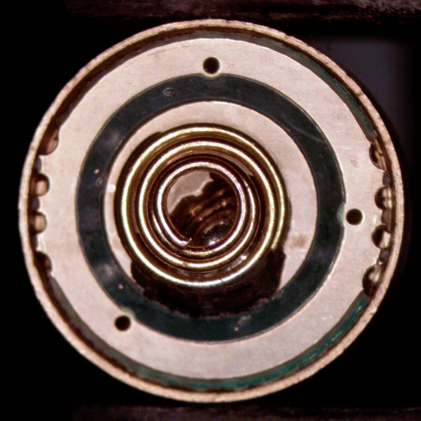
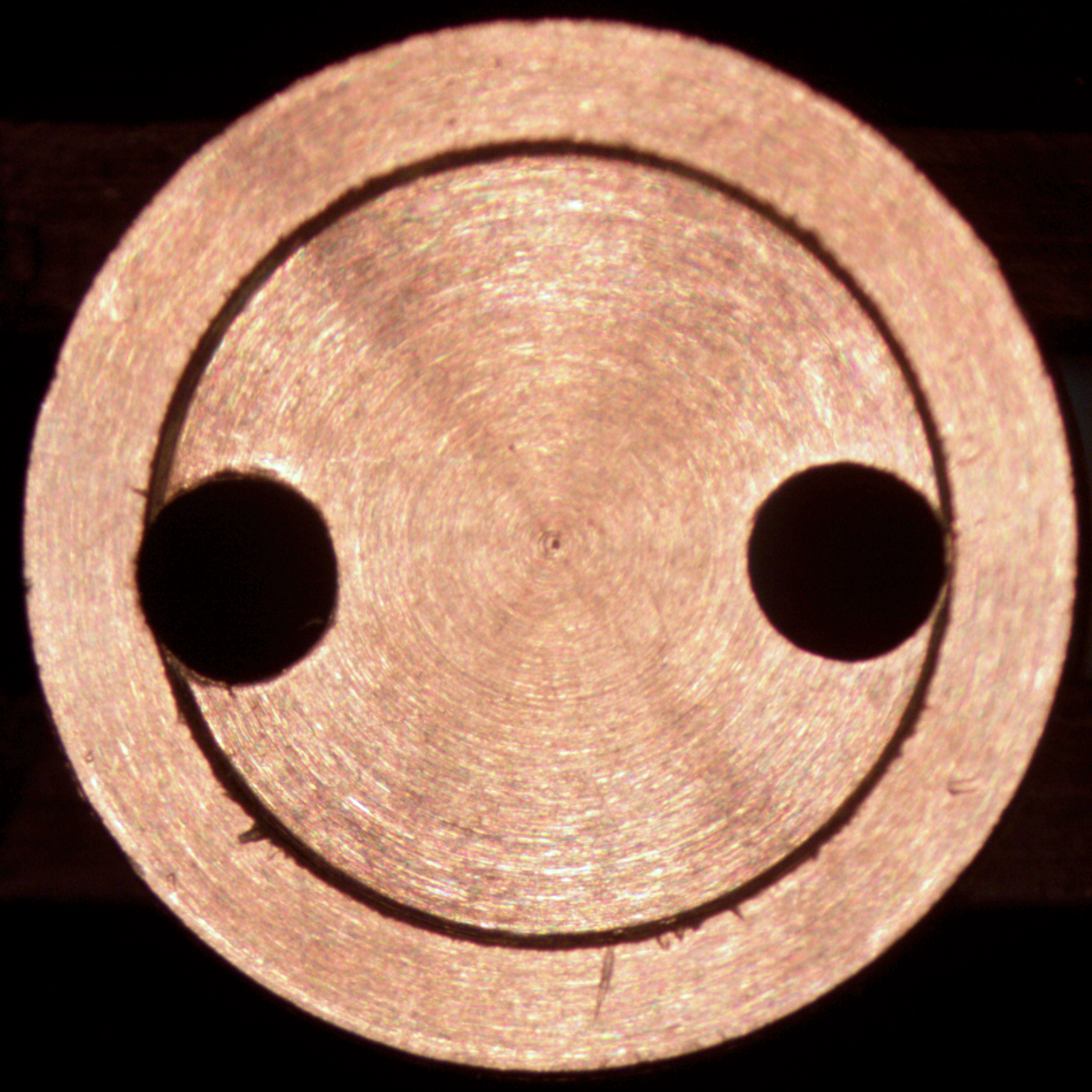
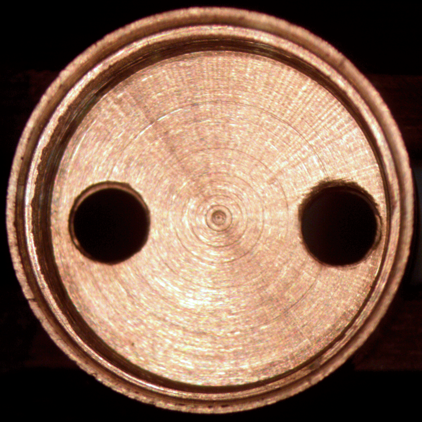
The pill is easy to disassemble: after desoldering the wires on the emitter PCB, gently wiggling the spring on the driver PCB will pull the driver out (mine was a simple friction fit). The emitter PCB sits in a shallow cavity on the top of the brass pill and mine had a liberal amount of thermal compound (to be honest, a bit overzealous). The driver PCB sits on a thin ledge machined into the interior of the brass pill (see below). My emitter PCB had a very messy reflow job, with lots of excess flux, solder blobs, and other gunk.
|
|
|
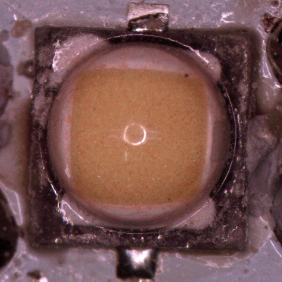
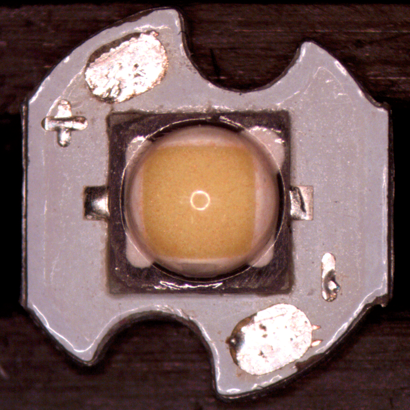
After disassembling the pill, I brushed off all the crusty thermal compound and cleaned up the emitter PCB and pill. The emitter PCB appears to be an aluminium MCPCB, 0.92mm thick.
|

|
|
|
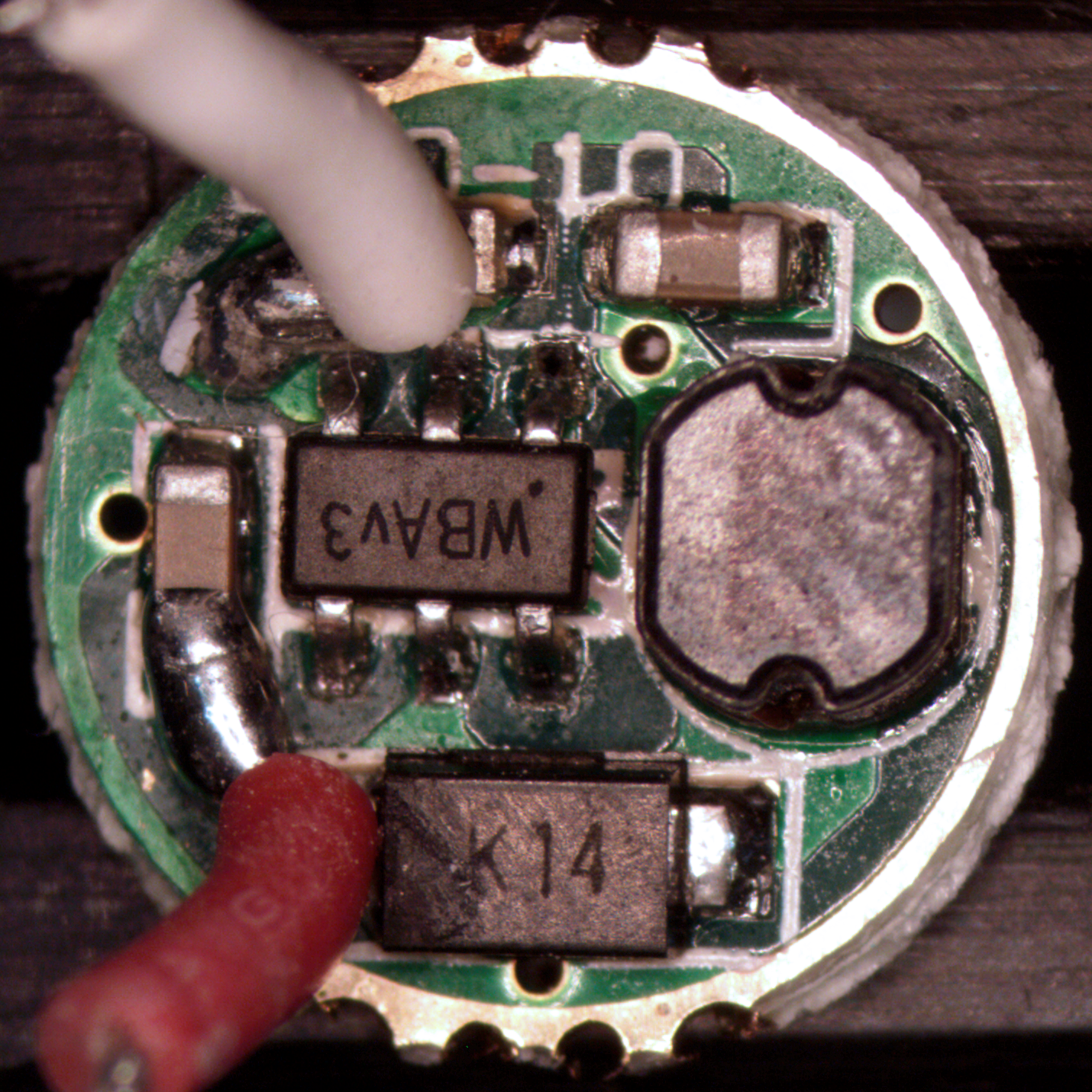
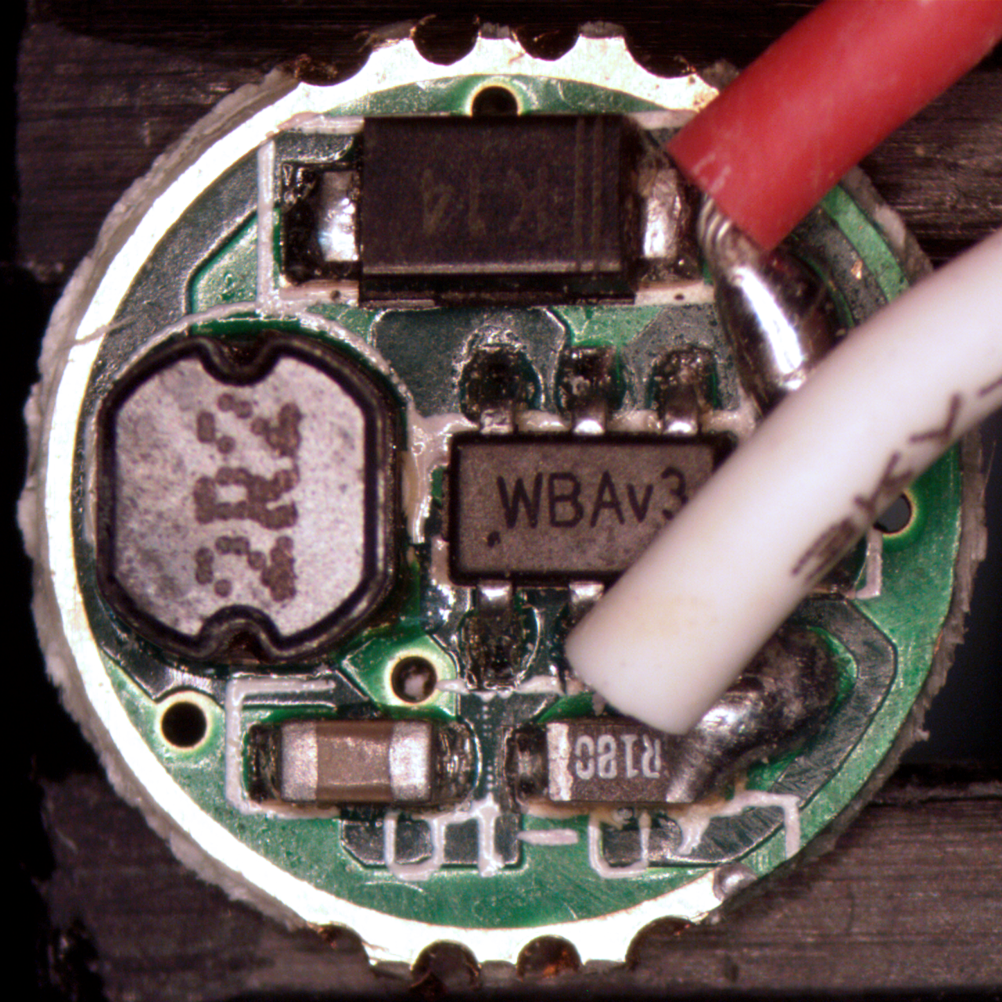
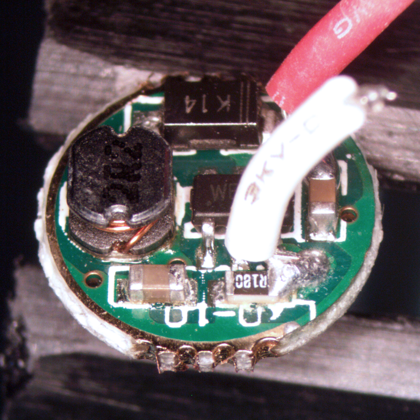
The driver is a single mode boost driver, has a pretty self-explanatory appearance. There’s an unidentified boost controller (I haven’t found a part that matches the package code WBAv3 but there are a few parts that have a possibly matching pinout) in SOT23-6, a 2.2µH inductor, Schottky diode, input and output caps, and a 180mΩ feedback resistor. In short, nothing surprising.
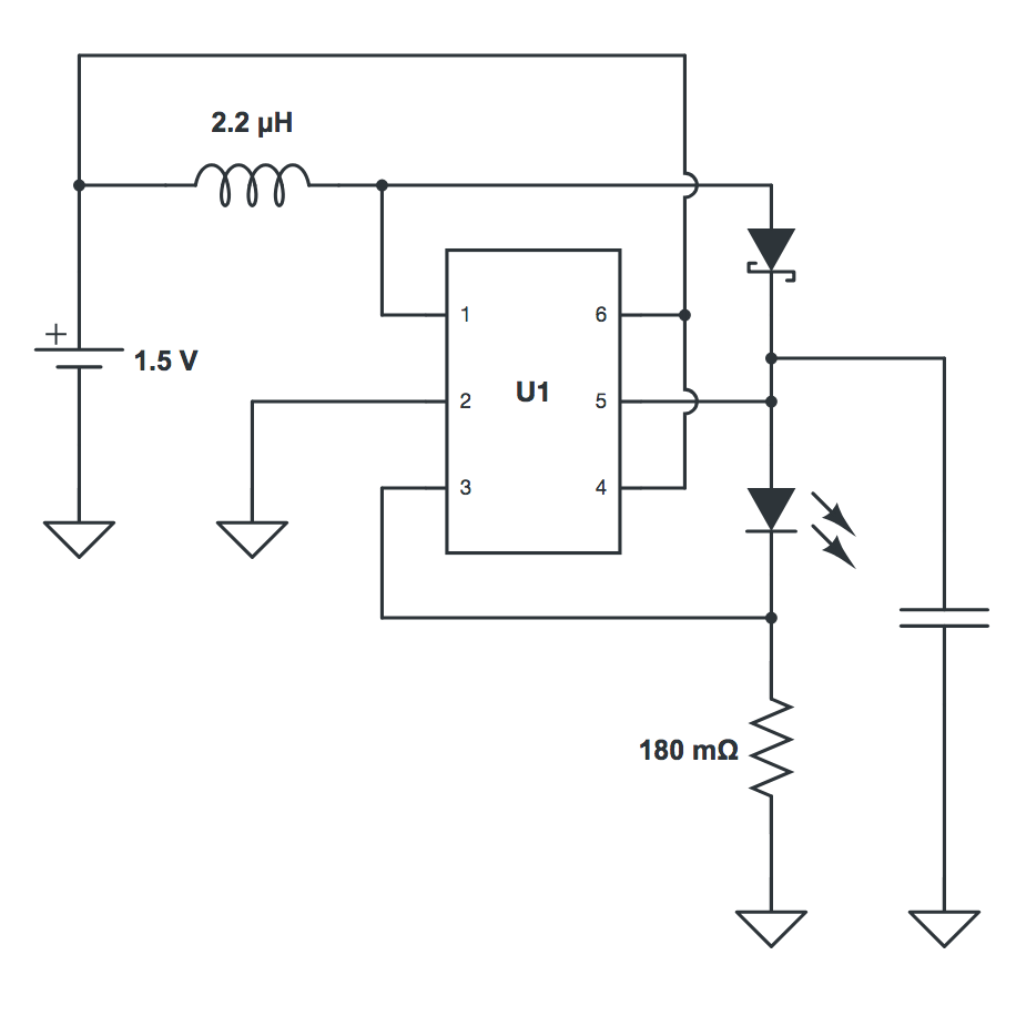
This is a rough draft of the schematic. May not be entirely accurate; I made this after giving the board a quick once-over, but there’s not much to it anyway. Actually, it’s definitely not accurate because the input decoupling cap is missing; I’ll redraw it tomorrow. (Side note: if anyone has a schematic, or better yet, a BOM for this driver, please let me know!)
|
|
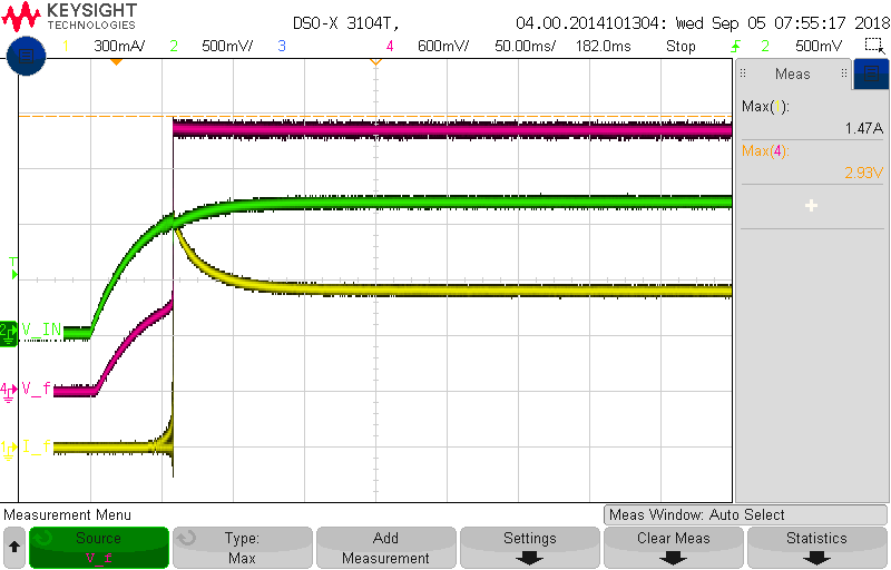
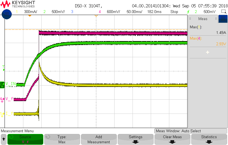
I was curious about the startup behaviour of the converter, so here are plots of \(V_{IN}\), \(V_F\), and \(I_F\) at \(V_{IN}\) = 1.2V, 1.5V, respectively. Keep in mind these are captured with an external lab supply and do not capture switch bounce or battery internal resistance.
Driver electrical measurements
Curiously, this driver appears to driver harder at lower voltages. I am admittedly a little skeptical of this data; I may need to go back and measure again to see if I can characterize this better. I was measuring forward LED current with a current probe and this may have introduced inaccuracies. It’s worth noting that the driver would not start up at \(V_{IN}\) < 0.9V but would happily run lower than 0.9V if started at a higher voltage. May require further investigation, but also doesn’t matter much.
| \(V_{IN}\) (V) | \(I_{IN}\) (mA) | \(V_F\) (V) | \(I_{F(avg)}\) (mA) | \(I_{F(ripple)}\) (mA) |
|---|---|---|---|---|
| 0.90 | 1101 | 2.75 | 1090 | 3.4 |
| 1.00 | 1208 | 2.77 | 1180 | 17.7 |
| 1.10 | 970 | 2.78 | 959 | 14.9 |
| 1.20 | 832 | 2.78 | 815 | 13.3 |
| 1.30 | 745 | 2.77 | 729 | 11.6 |
| 1.40 | 672 | 2.77 | 659 | 11.0 |
| 1.50 | 612 | 2.77 | 603 | 12.2 |
| 1.60 | 567 | 2.77 | 554 | 11.6 |
Further work
The motivation for this teardown was to investigate the possibility of a multi-mode 348 driver. I believe it’s feasible, but requires some careful component selection. Given the usable board area is a single side less than 1cm diameter, it’s certainly challenging. More to come.