Sofirn SP32A V2.0 Emitter Swap
I used the Sofirn SP32A V2.0 frequently for a few weeks, and then swapped the emitter to match my TH20 headlamp because I’ve been using them together quite a bit. It’s an easy emitter swap and illustrates the process well so I wanted to make a detailed write-up of the emitter swap as well. In this case, I am going to swap in a Nichia 21C LED, 4000K R9050, which is what my TH20 has. The Nichia 219C has a very similar footprint to the stock Cree XP-L2 LED, similar enough that we can simply remove the Cree emitter and reflow the Nichia. If you want to put in an emitter that doesn’t have the same footprint, you need to swap out the MCPCB as well.
Note that this mod is not endorsed by Sofirn, and definitely voids your warranty. If you break your light doing this, you can try asking the kind folks at /r/flashlight or BudgetLightForum. Swapping emitters should be pretty straightforward but I guess it’s possible to irreparably damage your light if you do something very wrong.
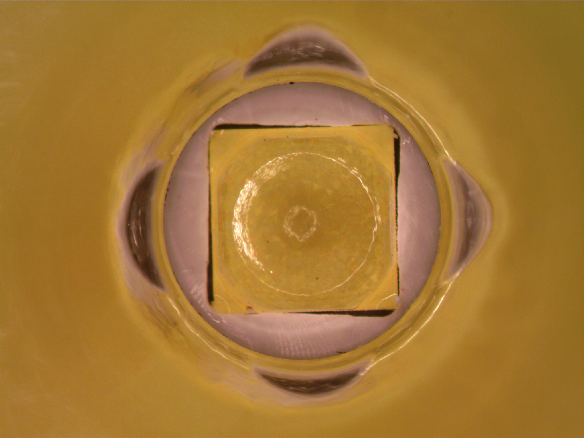
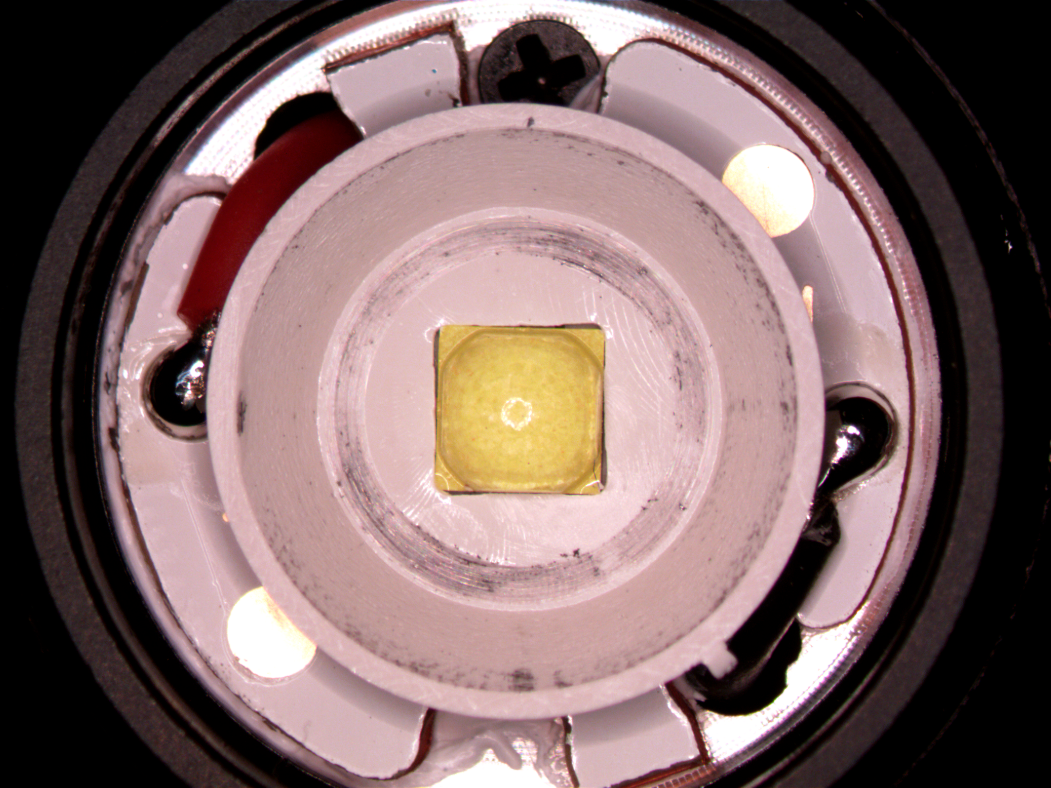
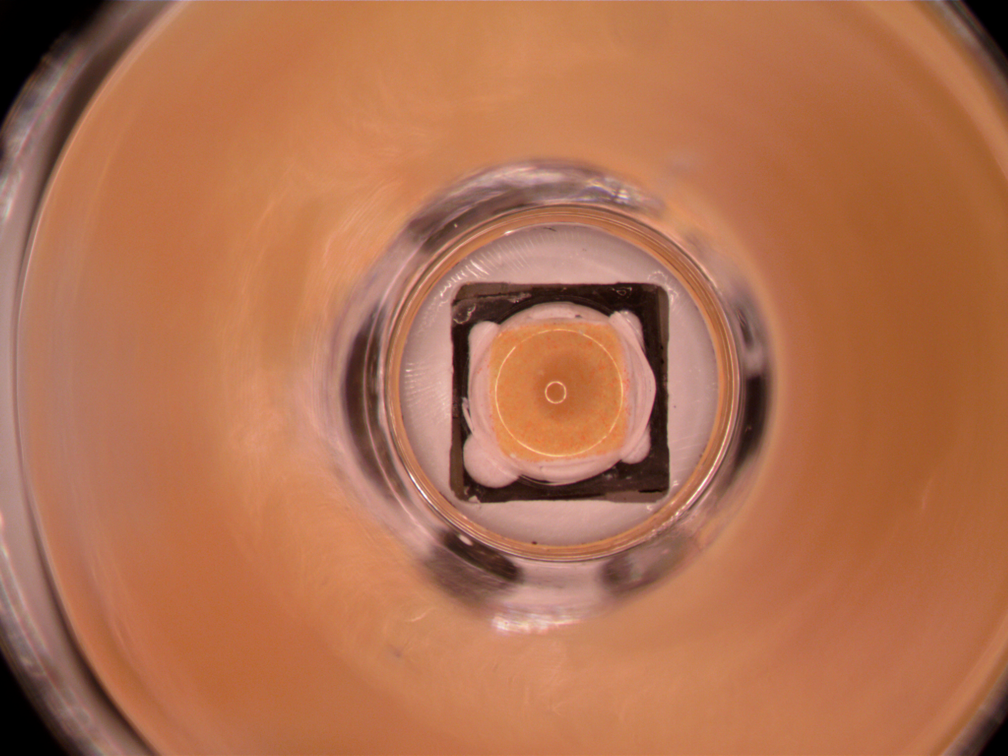
Looking into the light. The emitter is in the center, the white plastic surrounding it is the centering ring. We want to make that emitter prettier.
Disassembly
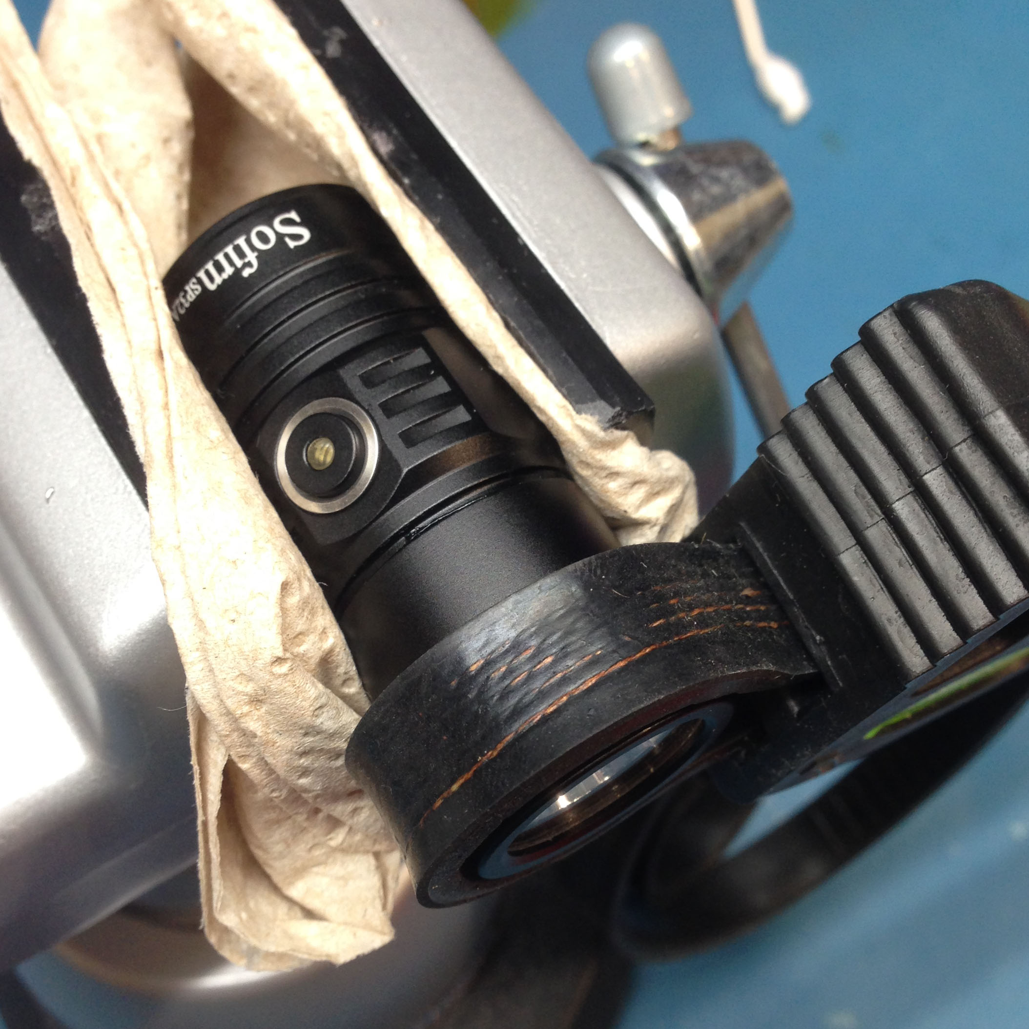
First things first, we need to get down to the emitter MCPCB. The SP32A has a bezel that screws on and holds the reflector and glass lens to the front. This bezel element has some mild threadlocker (at least, mine did, YMMV) but a little torque will sort it out. I highly recommend buying a cheap pair of strap wrenches (I use the Harbor Freight strap wrench set) but you may be able to loosen the bezel with a lot of elbow grease and some rubber grips.
|
|
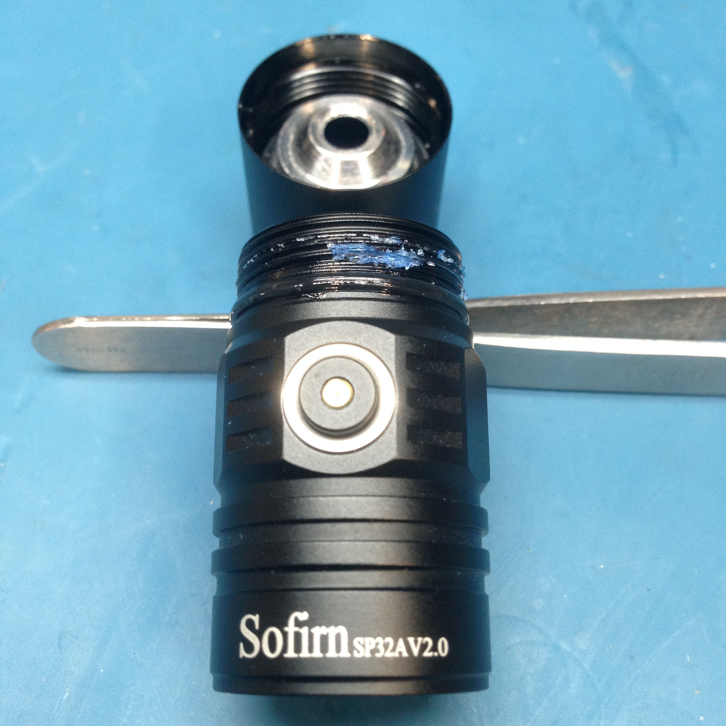
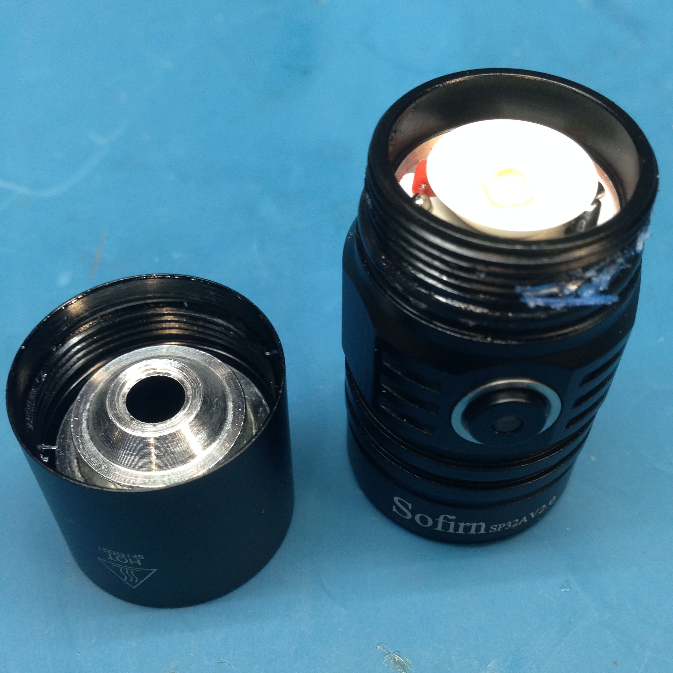
Carefully unscrew the bezel, the reflector and front glass will be loose. The blue gunk you see is the threadlocker, it’s best to clean it off so the light goes together smoothly at the end.
|
|
|
|
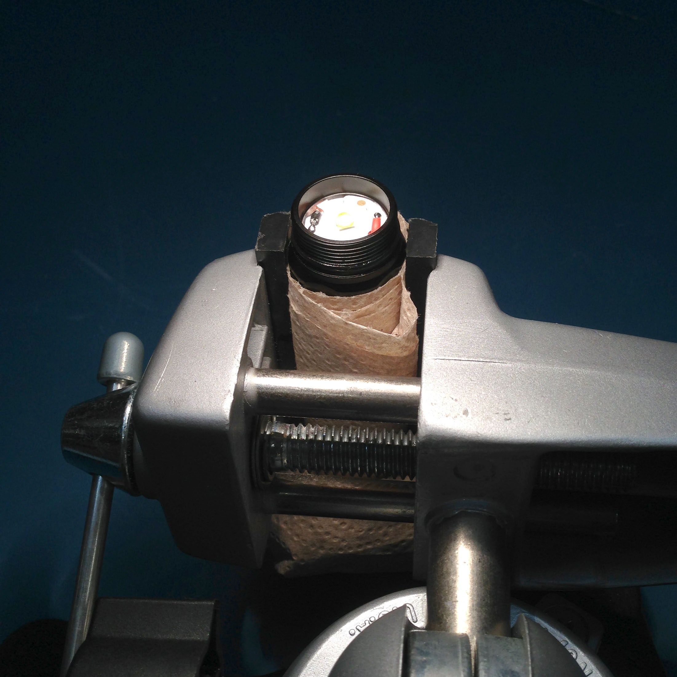
Set aside the bezel, glass, and reflector. The centering ring (the white plastic part surrounding the emitter) may remain on the emitter, set it aside as well. If you have it, a vise is helpful to hold the light still while desoldering the emitter PCB.
MCPCB Removal
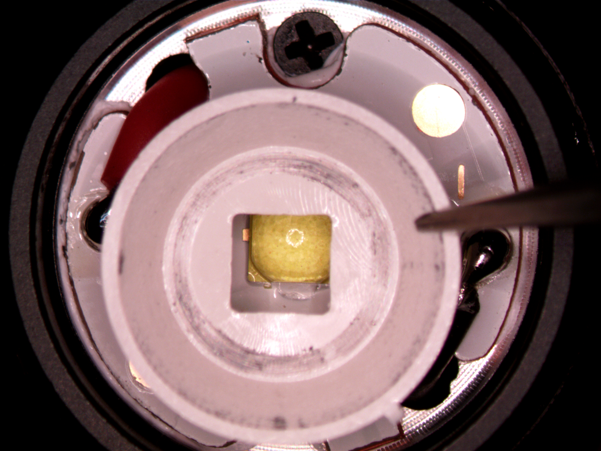
The emitter MCPCB sits in the head of the light, held in by two wires and the surface tension of the thermal paste underneath. We need to unsolder the wires, push them out of the way, and lift the MCPCB out.
Here, I use a dental pick and tweezers to push the wires away as I heat the solder joint, and then lift the MCPCB out. I also apply flux to the solder joints before heating them, which helps the solder flow on the tip, and therefore helps transfer heat more quickly. Because it’s an MCPCB with a thermal interface to the body of the flashlight, heating this joint may take a while, especially with a smaller or non-regulated iron.
Stock Emitter Removal
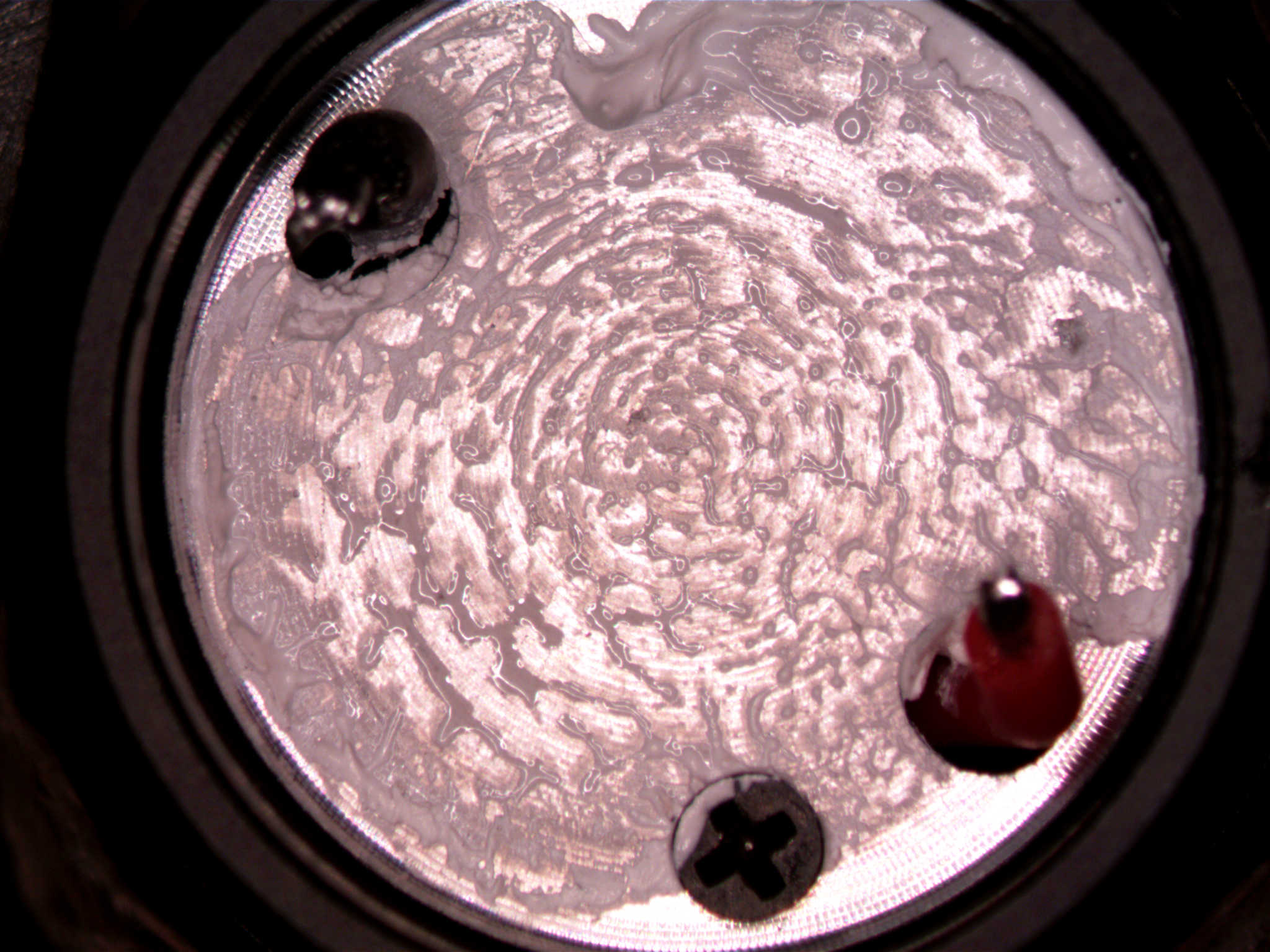
I’m using a hot air reflow setup to heat the MCPCB from below (heating it from the top can blister the soldermask or send the LED flying). When I see bubbles coming from underneath the emitter, I poke it with a pick to make sure it’s loose, then pluck it off. Next, I add flux and flow a small amount of solder onto the pads. Too much solder and the emitter will not sit flat, and possibly short out. I then attempt to clean the board before the solder is solid, so I have to reflow the solder again. The goal is nice, shiny, very slightly convex pillows of solder on each pad.
New Emitter Reflow
With pads prepared, I add more flux and place the LED over the pads. Different LEDs use different markings for polarity. In this case, the big dot in the corner is a cathode mark. Once the LED is placed, I heat from the bottom as before. When the solder flows, I tap the emitter to push some excess solder out (the little beads). Once the board cools, I check the emitter with a multimeter in diode check mode to make sure it flowed well, then clean flux off the board. If you don’t have a diode check mode on your multimeter, you can use a ~3V DC source and a resistor. Measure the voltage across the LED when it’s lit up. If it’s near or less than 3V, it’s good. If it’s 0V, or the LED doesn’t turn on, you either have a short or an open connection and you should desolder the LED, reflow the pads with solder taking care to make them all the same height, and then reflow the LED on again.
MCPCB Insertion
The MCPCB goes back the way it came out, taking care to get the polarity correct (Sofirn is kind enough to have polarity symbols on the MCPCB). Once it’s soldered in, you should be able to turn on the flashlight. Assuming you checked with a multimeter before hand, it’s pretty unlikely that the light won’t work. However, if the LED is very dim, you may have a bad connection. Pull it out and reflow it again.

If it works, reinstall the centering ring and put the light back together.
Summary
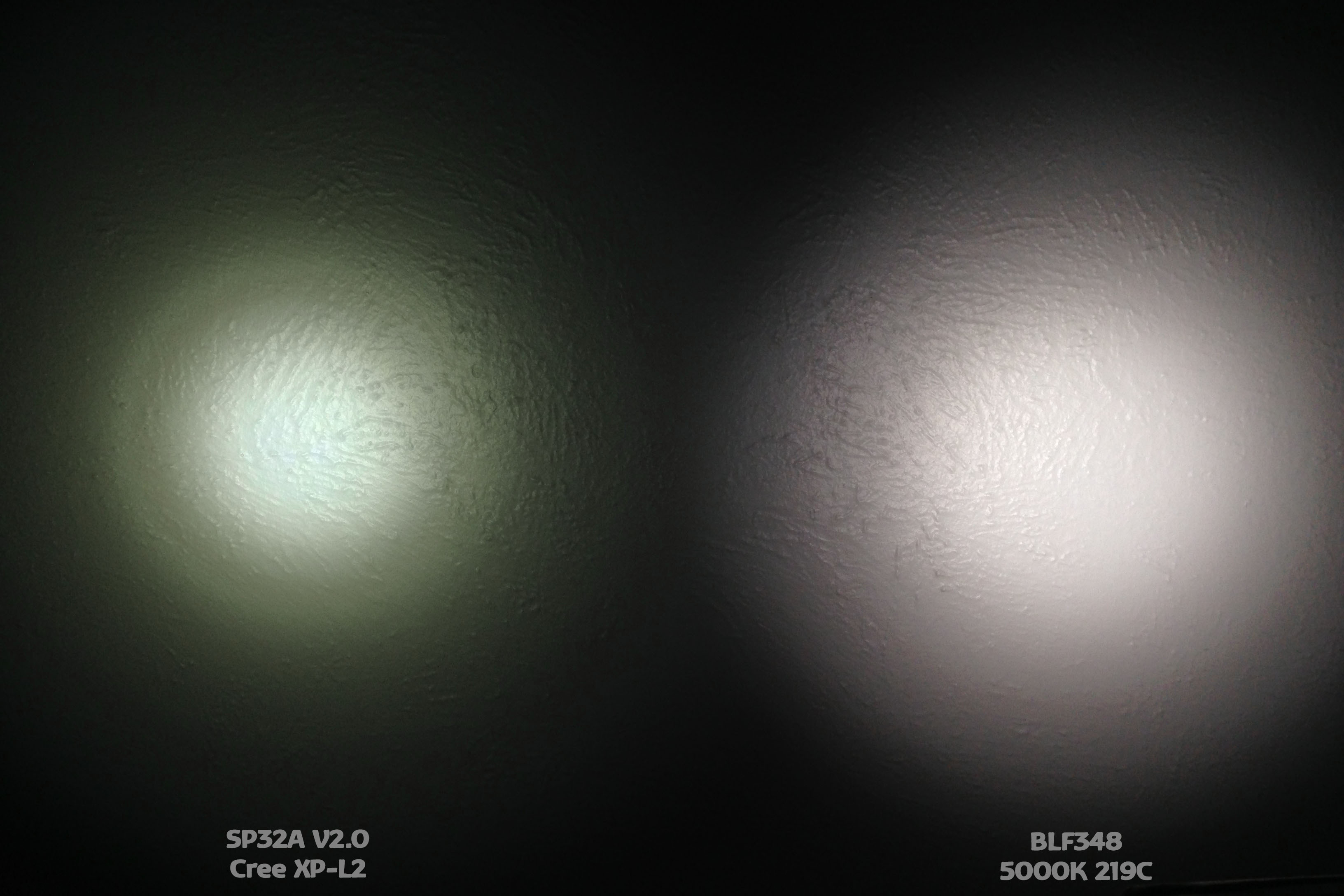
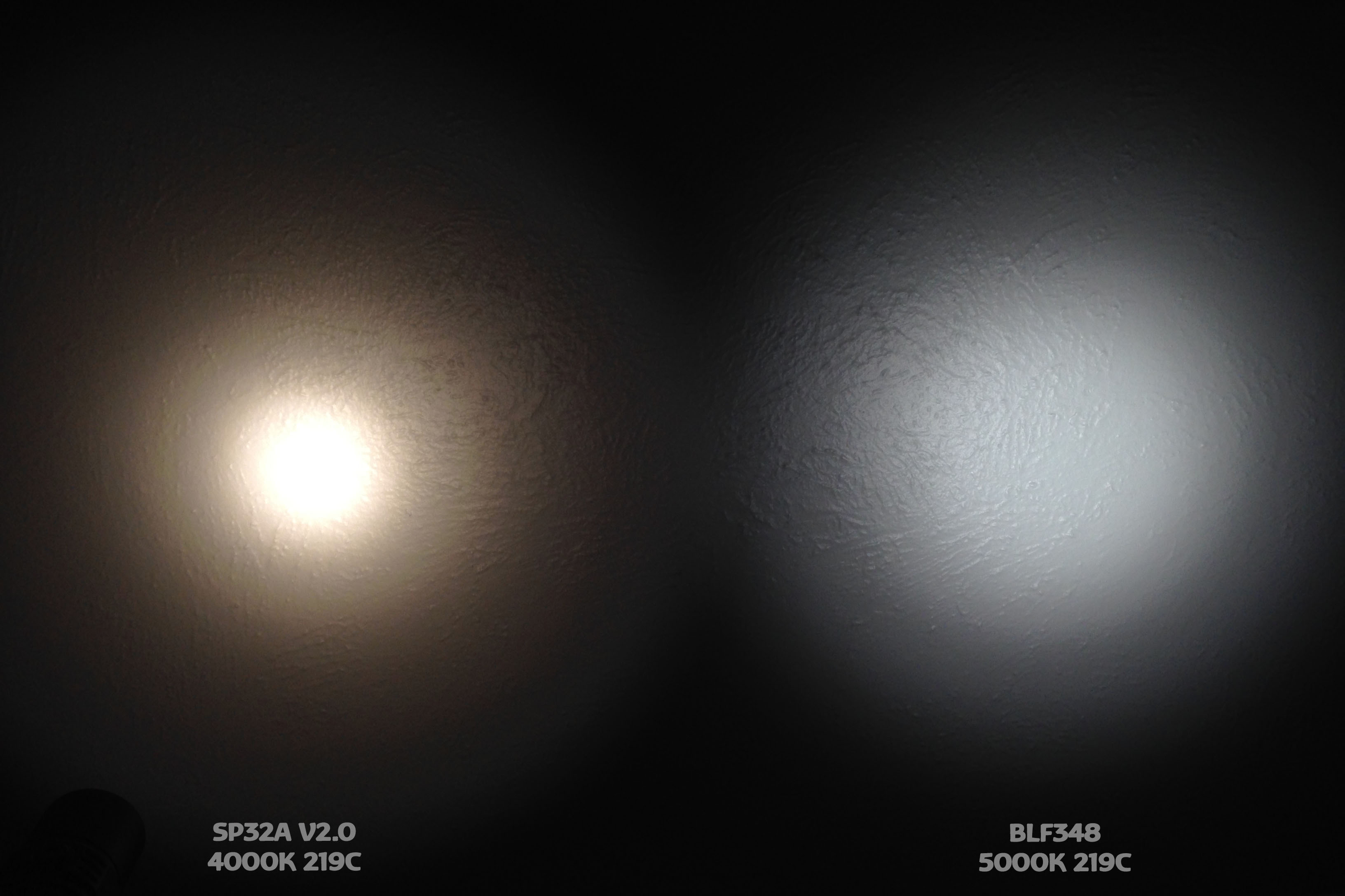
With the Nichia 219C, the beam has a much more even tint, although there is still a slight tint shift from the AR-coated glass and some ringing artifacts from the smooth reflector. As I mentioned above, I wanted 4000K to match my TH20, so it’s very warm next to my 5000K BLF348. I’m very pleased with the new emitter, and I like the SP32A V2.0 even more now. The only sticking point is the lack of a good sublumen mode, the lowest mode is still quite high. Nevertheless, the SP32A is a great light and even better with a new emitter. I would guess that a Samsung LH351C/D would be a good swap for this light, probably better than the 219C (slightly higher efficiency, same CRI).
|
|
If a picture is worth a thousand words, hopefully a video is worth a few more than that. I’ve done my best to capture the soldering process with video. This makes it harder for me, because I would ordinarily look through the microscope while doing this rework. However, I’m not fortunate enough to have a trinocular microscope; I have to do the soldering without the usual visual aids. So I blame that for all the shakiness :) Despite all that, I hope this helps explain the process, particularly for those that aren’t familiar with the reflow process.